Analog Inputs | Standard Automation
|
|
|
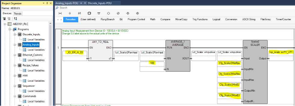
Analog Inputs can be programmed in the Analog_Inputs program (highlighted blue below). Each input has an AVERAGE and SCALER programming block. The first tag on the left is the actual PLC input tag. The number highlighted on the AVERAGE block is the number of samples used to create the average signal. This is to level out any signals that may be a bit noisy. The SCALER block is the block that scales the raw electrical signal to the Engineering Units for the input device. For examples of analog input scaling, see the Wiring Analog Inputs section. On the righthand side, this should be the name of the input used throughout the PLC logic when needed. Note – Be sure to set the Initial Values for Cfg_Scalor2MinRaw, Cfg_Scalor2MaxRaw, Cfg_Scalor2MinEU, Cfg_Scalor2MaxEU in the Global Variables to the correct scaling numbers required. |

